
Helicopter Wake Turbulence
Wake vortices from helicopters
A dangerous but neglected phenomenon
Case study of an EC135, in which a paraglider had a fatal accident during a rescue mission due to the wake vortex of the helicopter at more than 70 meters (!) from the approaching helicopter.
by Roland Vietzke, AIRBUS Helicopters
Preliminary Remarks
The final report was published by the BEA (1) in June 2021.
Together with the BEA, a safety promotion video was developed and published for this accident.
The following article presents the aircraft accident investigation from Airbus Helicopters' point of view.
Accredited by the BFU (2) Airbus Helicopters was in charge with two accident investigators and thus decisively involved in finding the cause.
In cooperation with iwiation®, the accident sequence could be decisively reconstructed based on the evaluated witness statements and the resulting simulations as well as the calculations of Airbus Helicopters.
All results of the investigation by Airbus Helicopters can be found in the BEA final report.
Preface
The following report reflects the Airbus Helicopters perspective into the air accident investigation of an EC135 in EMS (3) configuration that brought down a paraglider pilot during a rescue mission approaching Le Conquet beach.
The Accident Flight
The helicopter had been called to a rescue mission to treat an injured person on the beach of Le Conquet.
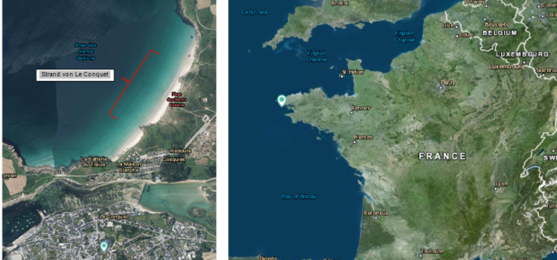
Figure 1: The beach of Le Conquet Source Airbus
The experienced pilot had made numerous flights and approaches to locations outside airfields and was familiar with the area between Brest and Le Conquet. The execution of the mission seemed to be simple. During the flight preparation, he had received all the necessary information (weather reports, airspaces) that allowed him to make the decision to carry out the rescue mission. No specific information was available about potential hazards at the mission site. Immediately after takeoff, he flew on a direct route to the mission destination where the casualty was to be picked up and decided to land on the beach in the immediate vicinity of the casualty.
In order to lose little time and be on site quickly, the pilot chose a low altitude. From this position, he transitioned to a semi-direct approach with a constant angle of descent. Approximately 2 NM (4) east of the site, he initiated the descent. This trajectory limited the field of view to the beach, which was obscured by the adjacent ridges, some tall trees and houses.
During the approach, the pilot and the technical flight attendant noticed kite surfers on the water on the left side (sea side). After passing the last altitude range and on final approach to the accident site, the pilot saw a paraglider in front of him on the right side (land side). To avoid a collision with the kite surfers and the paraglider, the pilot assigned a task to each person on board.
The helicopter was flying at an altitude of 170 feet (5) above the beach, while the paraglider was about 300 meters in front of him and to the right.
The pilot's decision to perform a semi-direct approach at a constant angle without conducting a reconnaissance by flying over the terrain left him with a limited choice of flight maneuvers from the moment he became aware of the kite surfers and the paraglider.
He had two alternatives:
To abort the approach with a go-around (6) in order to approach the beach with a new approach after the situation had been cleared, or to continue his final approach and land. He rejected the go-around because he believed that turbulence from the helicopter's downdraft could interfere with the paraglider's flight. He felt that the risk to the paraglider pilot was less if he continued his landing in the identified spot because he had the paraglider in sight, to his right, and slightly below the helicopter.
The paraglider pilot was in a slope gliding path and flew back and forth along the beach near the cliff. It can be assumed that he did not see the helicopter as he was flying south and since the helicopter was higher than him at that time and was to his right.
In this constellation, the paraglider pilot could neither turn left, as he was slightly below the cliff and had tailwind, nor turn right, as the helicopter was there.
The fact that the paraglider pilot did not perform any escape maneuver may also indicate that he was unaware of the danger posed by the helicopter's wake vortex at that moment, which was shifted toward him by the prevailing wind in the direction of the cliff.
Witnesses on the ground stated that they saw the helicopter approaching the beach at a low altitude while the paraglider pilot was flying in the direction to the helicopter about 70 m away from it and in parallel to the cliff. A few seconds after the helicopter and paraglider passed each other, these witnesses saw the wing of the paraglider close "like a book" and the paraglider plummet to the ground.
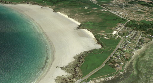
Figure 2: The accident beach in Le Conquet Source Google
|

Figure 3: Rescue helicopter approach Source BEA
|

Figure 4: Kite surfer on the beach Source BEA
|

Figure 5: Accident scene - Helicopter & Paraglider Source BEA
|

Figure 6: Flight path and calculated wake vortex of the helicopter Source Airbus
The blue coloration in Fig. 6 shows the wake vortex behind the helicopter which developed during the approach (black line) over the beach to its landing site. The wake vortex was displaced by the northwest wind in the direction of the paraglider and finally crossed its flight path. The bearing surface (wing) of the paraglider became unstable and collapsed when the helicopter no longer appeared to pose a threat.
The simulation showed that the induced air velocities near the paraglider reached values above the maximum variation amplitudes that the paraglider could handle, varying in direction and amplitude in short succession.
The investigations have shown that the effect of the wake vortex of a helicopter can, on the one hand, occur spatially at relatively large distances and, on the other hand, also act temporally over a relatively long period of time after the approach to the helicopter has occurred.
The pilot of the paraglider was surprised by the collapse of his wing, while the helicopter had already moved further away from this position.
The investigation also showed that there is a lack of general information about wake vortices, even in the rotorcraft community, and a lack of awareness of the hazards of wake vortices to helicopters, which often fly in close proximity to other aircraft.
Description of aerodynamic phenomena of helicopters and blade tip vortices
Each aircraft breaks through the air mass to generate lift to fly. This disturbance causes wake turbulence. Aircraft have staggering rules based on their size and weight to protect the lightest from the wake turbulence of the heaviest. Helicopter pilots are aware of the disturbances they cause near the ground. However, less well known and often underestimated is the danger their wake turbulence poses in flight.
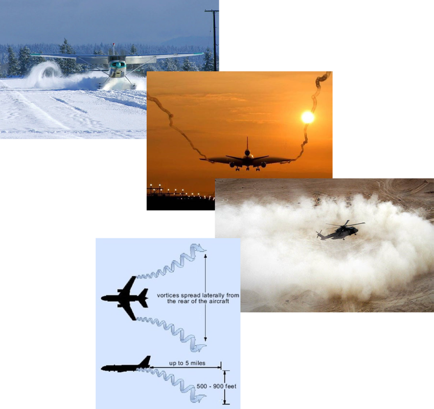
Figure 7: Air turbulence on aircraft in flight Source Airbus
Aviation rules ensure collision protection for all aircraft by pilots and ATC (7)
The influence between aircraft is limited by regulations: Aircraft must be kept separated in time and space near the ground so that the largest aircraft do not increase the risk of a crash due to turbulence for the lightest aircraft. For this reason, for example, there are minimum distances that must be maintained when aircraft take off and land.
Helicopter pilots are aware that they can kick up dust and/or objects near the ground, and that people on the ground must be vigilant.
However, wake vortices during helicopter flight are underestimated by pilots or are not known at all or rather in terms of direction, length, duration and induced airflow.
How is a helicopter wake vortex created and what is the risk involved, and for whom?
Overall view H135 and air movements near the rotor
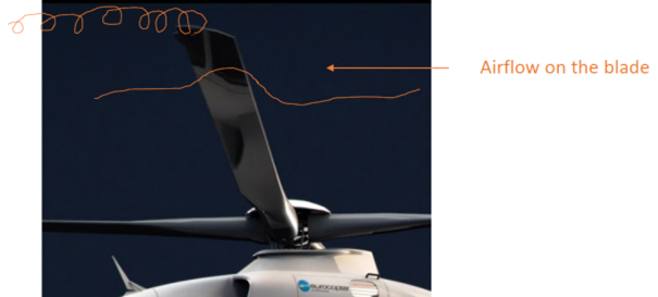
Figure 8: Helicopter hovering - single blade view Source Airbus
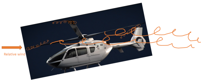
Figure 10: Helicopter in forward flight - airflow downward and backward Source Airbus
|
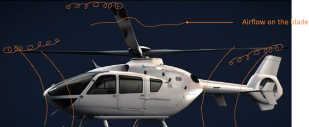
Figure 9: Helicopter hovering with exclusively vertical airflow Source Airbus
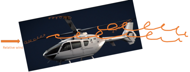
Figure 11: Larger wake vortices with increasing takeoff mass and speed Source Airbus
|
The calculation of wake vortices
Due to the computational boundary conditions, the flight was simulated with the Unsteady Free-Wake / Panel-Method Simulation Tool UPM (Unsteady Panel Methods) of the DLR (German Aerospace Center). The flight path is based on the time-aligned FDR (Flight data recorder) GPS data. In addition to the time alignment, due to the limited number of digits in the GPS position records, the accuracy of the trajectory over time had to be improved by an acceleration-based analysis and smoothing process.
|
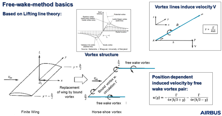
Figure 12: Free-Wake/ Panel-Method Source Airbus
|
The method using iwiation®
Reconstructing the aircraft accident scenario is critical to determining the causes. Flight recorder data, radar data, and wreckage analysis can provide important clues.
However, in some accidents, not all or any of the aforementioned sources of information are available.
If the accident scenario cannot be reconstructed based on the available information, additional potential sources such as eyewitness statements or video recordings can be used. The globally unique Immersive Witness Interview (iwi®) method was developed to use eyewitness testimony and video information for trajectory reconstruction. The information is transmitted in a 3D environment using the Immersive Witness Analyzer (IWA). Flight path and attitude data are reconstructed based on the available witness/video information. In this process, the reconstructed flight path information also considers possible sources of error. The accuracy of the reconstruction is visualized by the error tunnel. Witness and video information can be of crucial importance if the position data is not complete or e.g., radar data is not accurate enough due to terrain reflections. In some accident cases, witness information supported the creation of the entire accident scenario based on witness statements observed on board the aircraft. The reconstructed accident scenario can quickly become complex and visualization can help provide material for documenting and explaining how the accident occurred. Real-time photorealistic visualization can help to better understand the accident scenario from different perspectives. Causes such as weather conditions, response time, detour, etc. can be analyzed in the Virtual-Reality- Environment. The reconstructed flight path and the entire accident scenario, including the terrain and aircraft geometry, are transferred into virtual reality and displayed in real time and photo realistically using Immersive Witness Realsim (IWR).
Wake vortices and iwiation® - A first in accident investigation
By and large, few tools are available to model helicopter wake vortices. Manufacturers use digital simulation tools during aerodynamics design and optimization, but their applications are generally limited to turbulence propagation around the helicopter (approximately a few rotor diameters), specifically to study the effects of helicopter turbulence on the helicopter itself. Airbus Helicopters' aerodynamic modeling tools, which existed at the time of the accident, did not fully allow airflow modeling in a larger helicopter environment. So, a newly industrialized simulation tool was needed, adapted to study wake vortex generation and propagation. The UPM (8) calculation method is used as standard at Airbus Helicopters for verification during helicopter development. A propagation of the vortices and wake vortices generated by the rotor blades was adapted for the first time far beyond the usual range of the helicopter environment to be considered for certification. For this purpose, Airbus Helicopters has elaborately developed the calculation method.
Since the wake vortex is mainly generated by the main rotor, only the latter was modeled and analyzed.
This work was done in two steps:
1.) Use of the available general EC135 model to determine the flight attitudes and the main rotor speeds based on the recorded flight path of the helicopter.
2.) Use of rotor positions and speeds in the wake turbulence simulation tool to determine the spread of the latter.
These two steps allowed the calculation of the pressure and airspeed distribution behind the path of the helicopter.
Several methods are possible to calculate air pressure and airspeed variations. To represent the rotor, Airbus selected the freewake methodology, which allows the best modeling of the interactions of the local air flows and inclusion of calculations, while limiting the numerical dissipation for a longer period. Airbus Helicopters had validated this methodology during simulations for another type of helicopter and also during the investigation of this accident with experimental tests in the wind tunnel.
For this accident, the calculation for the wind conditions was extended with the drift and the propagation of the single vortices to wake vortices and their effect on the paraglider still beyond the distance from the helicopter to the paraglider was verified and integrated into the iwiation® simulation.
For the modeling, the length of the wave vortex was limited to 230 m, because beyond this distance the influence is negligible (the paraglider was within this 230 m distance). The simulation was performed over a period of 28 s. The wind used was based on the estimates of Météo-France and their statements for the accident site, i.e., 15 kt (9) wind from 330°. The weight of the helicopter assumed for the simulations was between 2,300 kg and 2,750 kg, which allowed the lift force to be determined.
The image of the wake turbulence behind the main rotor shows that the wind pushes the generated turbulence towards the cliff (Figure 6) and in particular towards the point where the paraglider was located.
First, the position of the paraglider was estimated by evaluating the statements of the people present on site and the statements of the helicopter crew.
|
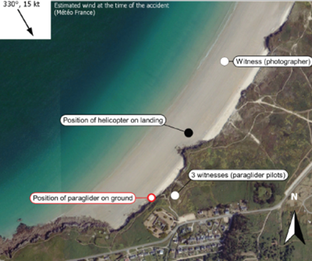
Figure 13: Position of the eyewitnesses and the paraglider Source BEA
|
After cross-checking the different indications, iwiation® estimated that the uncertainty regarding the position of the paraglider was three meters in height and five meters in width.
The simulation of the wake vortices of the helicopter carried out by Airbus Helicopters showed that during the final approach of the helicopter, the vortices displaced by the northwest wind propagated from the center of the beach to the cliffs.
The simulation also illustrated that the wake vortex of the helicopter crossed the path of the glider.
The flow velocities caused by the turbulence, which occurred before and at the time of the fall in the immediate vicinity of the paraglider pilot, reached values with different directions and amplitudes that were above the stability limit of the paraglider .
Continuation of the flight was most likely impossible under these conditions.
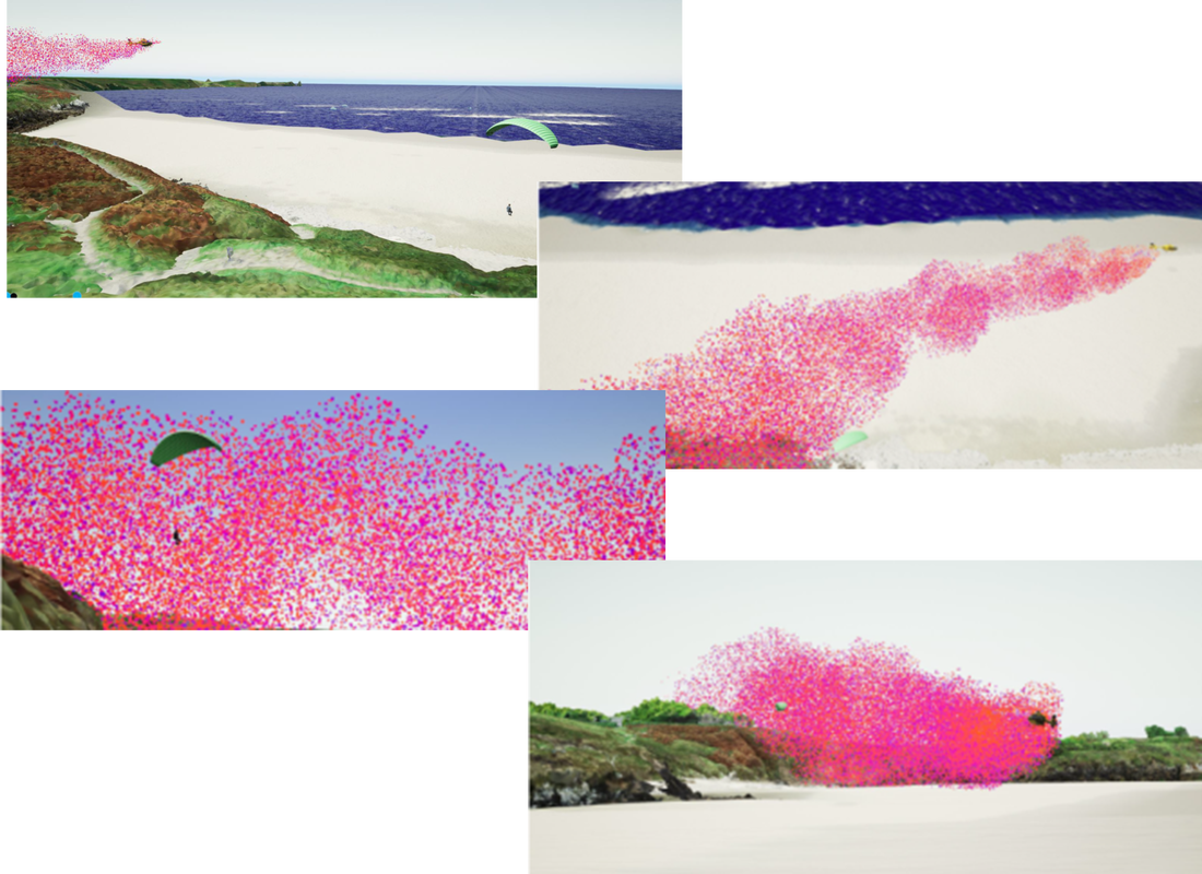
Figure 14: The accident sequence in the simulation Source Iwiation®
Summary
Aircraft lift produces a parasitic phenomenon called a wake vortex. It begins at the tips of the airfoil. In these zones, air flows from the bottom (highest pressure) to the top (lowest pressure), creating two vortices at the wingtips.
|
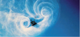
Figure 15 Helicopter with wake vortex Source STAC, 2016
|
Aircraft lift produces a parasitic phenomenon called a wake vortex. It begins at the tips of the airfoil. In these zones, air flows from the bottom (highest pressure) to the top (lowest pressure), creating two vortices at the wingtips.
Helicopters generate not only downwash but also backwash to the same extent; this becomes effective from a forward speed of about 10 kts.
The few published studies show that the wake turbulence of a helicopter is higher than that of an airplane of the same weight. In particular, the wake turbulence of larger helicopters is usually similar to that of commercial aircraft. Also, because of the tasks for which helicopters are used, they are more likely to be at a very close distance to other aircraft.
Therefore, consideration of the wake vortex phenomenon is critical to effective risk management for all stakeholders.
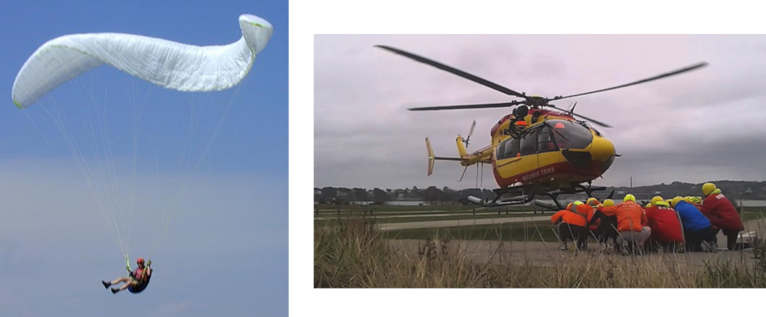
Figure 16 Paraglider with unstable chute - Helicopter on approach Source BEA
Important information for helicopter and light
aircraft pilots or paraglider pilots
Remember that the wake vortex is displaced by the wind. It affects the air in the flight path of your helicopter, but it is also distributed over a large area.
|

Figure 17 Wake vortices, source STAC, 2016
|